
Blog
How Long Does Electroplating Take? Calculate Plating Time and Thickness
Learn how to estimate electroplating time and coating thickness using current density, Faraday’s law, metal properties, and current efficiency.
Electroplating may take a few minutes or several hours. The required time depends mainly on the desired coating thickness, current density, plated metal, ionic valence, cathode current efficiency and the way current is distributed across the part.
Plating time increases approximately in proportion to the desired thickness and decreases as current density increases, provided the bath remains within its recommended operating range.
There is no universal answer such as “electroplating always takes 30 minutes.” A thin decorative deposit and a thick functional coating require very different amounts of deposited metal.
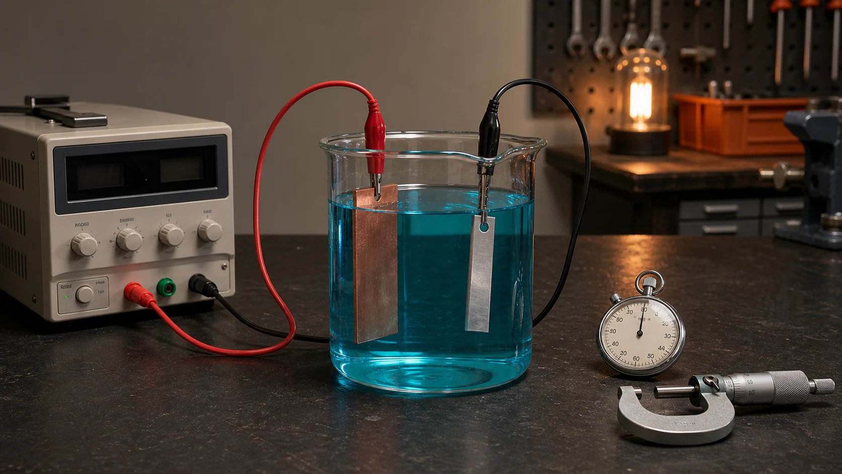 A practical plating-time estimate combines current density, target thickness and current efficiency, then checks the finished deposit by measurement.
Electroplating time calculation at a glance
A practical estimate requires the following inputs:
| Input | Symbol | Typical unit |
|---|---|---|
| Target coating thickness | h | µm or m |
| Current density | J | A/dm² or A/m² |
| Metal molar mass | M | g/mol or kg/mol |
| Deposited-ion valence | n | Dimensionless |
| Metal density | ρ | g/cm³ or kg/m³ |
| Cathode current efficiency | η | Decimal, such as 0.95 |
| Faraday constant | F | C/mol |
The principal time equation is:
t = (h × n × F × ρ) ÷ (η × J × M)
Where:
- t = estimated plating time in seconds
- h = target coating thickness
- n = number of electrons transferred per deposited metal ion
- F = Faraday constant
- ρ = density of the deposited metal
- η = cathode current efficiency as a decimal
- J = current density
- M = molar mass of the deposited metal
The NIST CODATA 2022 table gives the Faraday constant as 96,485.33212… coulombs per mole. The displayed value 96,485.33212 C/mol is sufficiently precise for the calculations in this guide.
Calculation summary
- Choose the required coating thickness.
- Measure the plated surface area.
- Obtain a bath-appropriate current density.
- Calculate total current from surface area.
- Calculate the ideal 100%-efficiency time using Faraday’s law.
- Adjust the estimate for realistic cathode current efficiency.
- Measure the finished deposit and refine the process estimate.
Why electroplating does not have one universal duration
Electroplating duration is determined by how much metal must be deposited and how quickly the selected process can deposit it.
A decorative flash coating may require only a small amount of metal. A functional deposit intended for wear resistance, dimensional restoration or corrosion protection may need considerably greater thickness. Doubling the target thickness approximately doubles the required electrical charge and plating time when all other conditions remain unchanged.
Different metals also have different molar masses, densities and ionic valences. One ampere-hour therefore does not produce the same coating thickness for copper, nickel, zinc or chromium.
The bath introduces further variation. Cathode current efficiency may be close to 100% in one process but significantly lower in another because part of the applied current is consumed by hydrogen evolution or other side reactions. The US Environmental Protection Agency’s electroplating documentation describes current density, plating time and cathode efficiency as important process variables.
Current density cannot simply be increased without limit to shorten the process. Operating above the bath’s validated range can cause:
- Burnt or dark deposits
- Roughness
- Powdery metal
- Excessive gas evolution
- Pitting
- Poor coverage in recesses
- Increased thickness variation
- Depletion of metal ions near the surface
Use the current-density range provided by the bath supplier or a validated process specification.
How are current, time and deposited metal related?
Faraday’s law relates the amount of metal deposited to the electrical charge passed through the electroplating cell.
Electrical charge is:
Q = I × t
Where:
- Q = electrical charge in coulombs
- I = current in amperes
- t = time in seconds
After cathode current efficiency is applied, the estimated deposited mass is:
m = (η × I × t × M) ÷ (n × F)
Where:
- m = deposited mass
- η = cathode current efficiency as a decimal
- I = current
- t = time
- M = molar mass
- n = number of electrons transferred per deposited metal ion
- F = Faraday constant
This equation shows why both current and time matter. Passing 2 A for 30 minutes supplies the same total charge as passing 1 A for 60 minutes:
2 A × 1,800 s = 1 A × 3,600 s = 3,600 C
That does not mean the two setups will necessarily produce deposits of equal quality. The higher-current setup also produces a higher current density unless the plated area changes, and it may exceed the bath’s recommended operating range.
How do you convert deposited mass into coating thickness?
For a uniform deposit, coating thickness is related to deposited mass by:
h = m ÷ (ρ × A)
Where:
- h = coating thickness
- m = deposited mass
- ρ = deposited-metal density
- A = plated surface area
Substituting Faraday’s law gives:
h = (η × I × t × M) ÷ (n × F × ρ × A)
Because current density is defined as:
J = I ÷ A
The thickness equation can be simplified to:
h = (η × J × t × M) ÷ (n × F × ρ)
Solving for time produces:
t = (h × n × F × ρ) ÷ (η × J × M)
This form is especially useful because it calculates plating time directly from target thickness and current density.
Unit consistency
ASTM electrodeposition guidance identifies micrometres as a coating-thickness unit, amperes per square metre as the SI current-density unit and amperes per square decimetre as a commonly used alternative plating-shop unit.
| Quantity | Recommended calculation unit |
|---|---|
| Thickness | metres |
| Current | amperes |
| Current density | A/m² |
| Time | seconds |
| Density | kg/m³ |
| Molar mass | kg/mol |
| Efficiency | decimal |
| Electrical charge | coulombs |
Useful conversions include:
- 1 µm = 1 × 10⁻⁶ m
- 1 A/dm² = 100 A/m²
- 1 g/cm³ = 1,000 kg/m³
Do not mix centimetres, decimetres and metres in the same equation without conversion. A unit error can change the result by a factor of 100 or more while still producing a number that appears plausible.
Worked example: How long does copper electroplating take?
Suppose a divalent copper plating process is operated under the following illustrative conditions:
| Input | Value |
|---|---|
| Target thickness | 10 µm |
| Current density | 2 A/dm² |
| Copper valence | 2 |
| Cathode current efficiency | 95% |
| Copper molar mass | 0.06354 kg/mol |
| Copper density | 8,930 kg/m³ |
| Faraday constant | 96,485.33212 C/mol |
The molar-mass and density values are consistent with the copper values used in the historical US Bureau of Standards electroforming calculation table. That table’s deposition factors assume 100% cathode current efficiency, so this example applies the separate 95% efficiency factor shown above.
Step 1: Convert the thickness
10 µm = 10 × 10⁻⁶ m
h = 0.000010 m
Step 2: Convert current density
2 A/dm² = 200 A/m²
Step 3: Convert efficiency to a decimal
95% = 0.95
Do not enter 95 into an equation that expects efficiency as a decimal.
Step 4: Enter the values
t = [(0.000010) × (2) × (96,485.33212) × (8,930)] ÷ [(0.95) × (200) × (0.06354)]
Step 5: Calculate the time
t ≈ 1,427 seconds
Convert seconds to minutes:
1,427 ÷ 60 ≈ 23.8 minutes
Estimated copper plating time: approximately 24 minutes.
This is a practical engineering estimate under the stated 95%-efficiency and uniform-distribution assumptions. It is not a guaranteed production time or a universal copper deposition rate. The actual result depends on the specific bath, temperature, agitation, additives, electrical contact and current distribution.
Worked example using surface area and total current
Consider a component with a total exposed plating area of:
A = 1.5 dm²
The selected bath current density is:
J = 2 A/dm²
Calculate the required current:
I = A × J
I = 1.5 × 2 = 3 A
For a detailed explanation of area measurement and current calculation, see How to Calculate Electroplating Current from Surface Area.
If the part is copper-plated for approximately 24 minutes using the same metal properties and illustrative 95% efficiency from the previous example, its estimated average thickness is approximately 10 µm.
Now suppose the plated area is doubled to 3 dm² while the current density remains at 2 A/dm².
The required total current becomes:
I = 3 × 2 = 6 A
The total current doubles because there is twice as much surface to supply. However, the estimated deposition rate per unit area remains unchanged because current density is still 2 A/dm².
At constant current density, increasing the plated area increases the required total current but does not independently change the predicted thickness deposited per hour.
If the power supply remains at only 3 A after the surface area doubles, current density falls to 1 A/dm², and the estimated plating time for the same thickness approximately doubles.
What is the difference between theoretical and actual plating time?
Faraday’s law provides the physical foundation, but an actual plating bath rarely behaves like a perfectly uniform theoretical model.
For the ideal Faraday-law result, set η = 1.00 and assume perfectly uniform current distribution. For a practical estimate, replace that ideal efficiency with a documented or measured bath-efficiency value. The finished coating must still be measured because neither calculation describes every local region on a real part.
Cathode current efficiency
Cathode current efficiency is the fraction of the electrical charge that deposits the intended metal.
At 95% efficiency:
η = 0.95
This means the calculation assumes that 95% of the charge contributes to metal deposition and 5% is consumed by other electrochemical reactions.
Lower efficiency produces less deposited metal at the same current and duration. The process must therefore run longer to achieve the same average thickness.
The EPA’s electroplating documentation provides a clear example at the extreme end: conventional hexavalent chromium plating may use only a small portion of the applied current for chromium deposition, while much of the current is consumed by hydrogen evolution.
Bath composition and metal concentration
A depleted, contaminated or incorrectly maintained bath may not perform like the original technical data sheet. Metal concentration, pH and additive balance can influence deposit quality and operating range.
Temperature and agitation
Temperature and agitation affect ion transport and the condition of the liquid layer directly adjacent to the part. A current density that works well in a controlled, agitated bath may produce poor results in a cold or stagnant solution.
Anode condition
Passivated, undersized or poorly positioned anodes can restrict the process and contribute to uneven current distribution.
Electrical resistance
Dirty rack contacts, thin wires, weak clips and oxide-covered connection points can create unstable current or localized heating.
Geometry and rack loading
Corners, projections, recesses, closely spaced components and shielding between parts all influence local current density. The total calculated current may be correct while individual regions receive significantly different shares of it.
Why is electroplated thickness not uniform?
The simplified equations assume that current is distributed evenly over the entire plated surface. Real parts rarely satisfy that assumption.
Edges, corners and projections commonly receive higher local current density. Deep recesses, internal corners and shielded surfaces may receive less. Parts can also interfere with one another when several components are placed close together on a rack.
Historical Bureau of Standards guidance explicitly warns that calculated thickness should not be taken at face value for irregular cathodes. Current concentrates on corners and edges, making those deposits heavier at the expense of other areas. The same guidance recommends using calculated time only as an estimate and verifying the finished deposit by measurement.
It is therefore important to distinguish three different thickness values:
| Thickness term | Meaning |
|---|---|
| Theoretical thickness | Ideal thickness predicted at 100% current efficiency with perfectly uniform current distribution |
| Estimated practical thickness | Ideal result adjusted using realistic cathode efficiency and validated process experience |
| Measured thickness | Thickness physically verified at one or more locations on the finished component |
An average calculated thickness of 10 µm does not guarantee that every location is at least 10 µm.
A specification may require a minimum local thickness, not merely a calculated average. When minimum thickness matters, measure the regions most likely to receive less current rather than checking only an exposed edge.
How can actual electroplating thickness be verified?
The correct measurement method depends on the deposited metal, substrate, thickness range, part geometry and required accuracy.
Coating-thickness gauge
Magnetic-field and eddy-current instruments can provide nondestructive measurements for suitable coating and substrate combinations. ASTM E376-26 covers these instrument types but does not imply that every gauge works with every metal pair. The electrical and magnetic properties of the coating and substrate determine whether a particular method is suitable.
Micrometer measurement
A micrometer can be useful where the part geometry permits accurate before-and-after measurements and the coating is sufficiently thick relative to the instrument resolution.
For a coating applied to two opposing faces, the dimensional increase may represent twice the thickness of one face.
Weight-gain method
Weigh the cleaned and dried component before and after plating. The deposited mass can be converted to average thickness:
h = Δm ÷ (ρ × A)
This method provides an average over the entered area. It does not show local thickness variation.
Cross-section measurement
A representative sample can be cut, mounted, polished and examined microscopically. This is destructive but can reveal local thickness and layer structure.
X-ray fluorescence
X-ray fluorescence can measure suitable metallic coating systems nondestructively, depending on the instrument, calibration, coating combination and geometry.
Coulometric measurement
Coulometric methods remove a known area of coating electrochemically and calculate thickness from the charge required. Applicability depends on the coating and substrate system.
The objective is not merely to confirm one calculation. Measurement creates feedback that can improve the efficiency assumption and timing used for later runs.
Common electroplating time-calculation mistakes
Entering efficiency as 95 instead of 0.95
An efficiency percentage must be divided by 100 when the equation expects a decimal.
Confusing current and current density
Current is measured in amperes. Current density is current divided by plated area.
Using the wrong area
Include every exposed surface that receives metal. Exclude properly masked or insulated surfaces.
Mixing units
Convert micrometres to metres, A/dm² to A/m² and g/cm³ to kg/m³ before using a fully SI equation.
Using the wrong ionic valence
Copper deposited from a divalent copper system uses n = 2, meaning that two electrons are transferred per deposited copper ion. A different deposited-ion state changes the electrochemical equivalent and therefore changes the calculated time.
Assuming 100% efficiency
A theoretical 100% value may underpredict the required process time. Use a documented bath value or determine efficiency experimentally.
Treating average thickness as minimum thickness
The Faraday calculation estimates an average under uniform-distribution assumptions. It does not guarantee thickness in recessed or shielded regions.
Increasing current density only to save time
Higher current density shortens predicted time but may push the bath or part geometry outside a stable operating range.
Using one generic deposition rate for every bath
A statement such as “nickel plates at a fixed number of microns per hour” is incomplete unless it also specifies current density, efficiency, valence and process conditions.
Practical electroplating planning checklist
Before calculating or starting a plating run:
- Identify the coating metal and exact bath chemistry.
- Confirm the valence of the metal ion being deposited.
- Measure the total exposed plated surface area.
- Select a current density supported by the bath specification.
- Define the target coating thickness.
- Use a documented cathode-efficiency assumption.
- Confirm that the power supply can maintain the required current.
- Calculate the estimated plating time.
- Prepare suitable ventilation, personal protective equipment, rinsing and spill controls.
- Plate and inspect a test coupon or noncritical part.
- Measure the finished deposit.
- Update the efficiency or timing assumption using the measured result.
Electroplating calculations do not replace the bath manufacturer’s technical data sheet, Safety Data Sheet, process testing or thickness inspection.
Calculate plating time and thickness with PlateLab
PlateLab provides a practical calculation companion for copper, nickel and zinc electroplating.
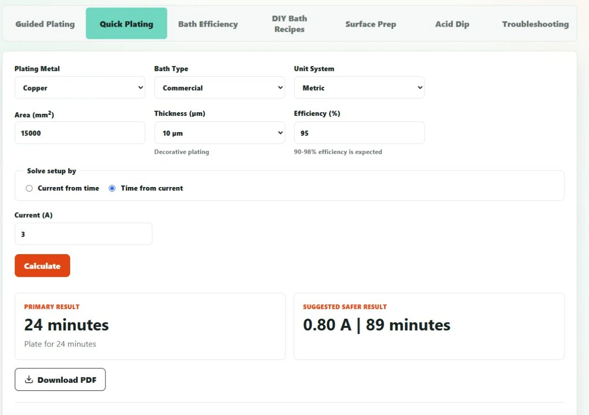 For the worked copper example, PlateLab estimates approximately 24 minutes using 15,000 mm² of area, 10 µm thickness, 3 A and 95% current efficiency.
Enter:
- Plating metal
- Surface area
- Target coating thickness
- Bath type
- Estimated or measured current efficiency
- Available current or desired plating time
PlateLab can then help you:
- Calculate required electroplating current
- Estimate plating time from a known current
- Determine the current required for a selected duration
- Compare different current-and-time combinations
- Record the assumptions used for the calculation
- Evaluate bath efficiency using measured thickness or mass gain
Use PlateLab to calculate electroplating current, estimate coating thickness and compare predicted deposition conditions before preparing the bath.
PlateLab applies Faraday’s law and practical process inputs, but it does not replace bath specifications, controlled test runs or physical thickness measurement. PlateLab itself describes differences in area definition, density, valence, efficiency and current density as common reasons why two calculators may return different results.
For the complete preparation and plating workflow, read How to Electroplate with PlateLab: A Step-by-Step Guide.
You can also use the PlateLab Bath Efficiency calculator to understand electroplating efficiency and replace an assumed efficiency with a value derived from measured mass or coating thickness. The PlateLab FAQ explains the calculator assumptions and common reasons why results may differ.
Frequently asked questions
How long does electroplating normally take?
Electroplating can take minutes or hours. The duration depends on target thickness, current density, metal properties, ionic valence and cathode current efficiency. A thin decorative coating may be relatively quick, while a functional or heavy deposit requires more charge. Calculate the time for the specific metal and bath rather than using a universal duration.
How do you calculate electroplating time?
Use:
t = (h × n × F × ρ) ÷ (η × J × M)
Enter thickness in metres, current density in A/m², density in kg/m³, molar mass in kg/mol and efficiency as a decimal. The result is in seconds. The current-density value and efficiency should come from the bath supplier, a validated procedure or measured process data.
How much thickness does electroplating add per hour?
There is no universal microns-per-hour value. After current efficiency is included, the estimated average rate is:
h ÷ t = (η × J × M) ÷ (n × F × ρ)
The result depends on the metal, current density, ionic valence, density and current efficiency. Bath condition and current distribution then determine how closely the actual local thickness follows the calculated average.
Does higher current make electroplating faster?
Higher current shortens plating time only when it produces a higher current density that remains inside the bath’s acceptable range. Excessive current density may burn edges, increase roughness, generate more gas or reduce uniformity. Do not increase current without considering plated area, geometry, agitation, temperature and the supplier’s process limits.
Why is the actual coating thinner than the calculation predicts?
The assumed efficiency may be too high, some current may be consumed by side reactions, the current may not have remained stable or the entered surface area may be inaccurate. Thickness may also be measured in a low-current region while the calculation represents the average over the entire part.
Does part size affect plating time?
At constant current density, part size does not independently change the predicted deposition rate per unit area. A larger part requires proportionally more total current. When the available current is limited, increasing the plated area lowers current density and increases the time required to reach the same average thickness.
How long does nickel plating take?
Nickel-plating time depends on target thickness, current density, nickel density, the nickel ion’s valence and the bath’s cathode efficiency. Different nickel formulations have different operating ranges, so there is no reliable universal duration. Use the specific bath data and Faraday equation, then verify the result on a test piece.
How can I measure electroplating thickness?
Suitable methods may include a calibrated magnetic or eddy-current gauge, micrometer comparison, weight gain, metallographic cross-section, X-ray fluorescence or coulometric testing. Method suitability depends on the coating, substrate and geometry. Measure more than one location when local minimum thickness or uniformity is important.
The engineering loop: calculate, plate, measure, refine
Faraday’s law provides a defensible estimate of plating time and thickness. It does not describe every local condition on a real component.
The strongest workflow is:
Calculate → Plate → Measure → Refine
Use the first calculation to establish a controlled starting point. Record the area, current density, current, time, bath condition and assumed efficiency. Measure the finished coating, compare the result with the estimate and update the next run.
Calculation predicts the deposit. Measurement closes the engineering loop.
Technical references
- NIST CODATA 2022, Faraday constant.
- US Environmental Protection Agency, AP-42 Section 12.20, Electroplating.
- US Bureau of Standards, Electroforming of Waveguide Components for the Millimeter-Wavelength Range.
- ASTM, Guidelines for Metrication in the Field of Electrodeposition and Related Processes.
- ASTM E376-26, Standard Practice for Measuring Coating Thickness by Magnetic-Field or Eddy Current Testing Methods.
- PlateLab FAQ and Guided Plating documentation.