
Blog
How to Calculate Electroplating Current from Surface Area
Learn how to calculate electroplating current from surface area using current density, unit conversions, worked examples, and PlateLab.
To calculate electroplating current, multiply the total exposed surface area of the parts by the current density specified for the plating bath. The formula is Current (A) = Surface area × Current density, or I = A × J. The units must match: an area in dm² multiplied by A/dm² gives current in amperes.
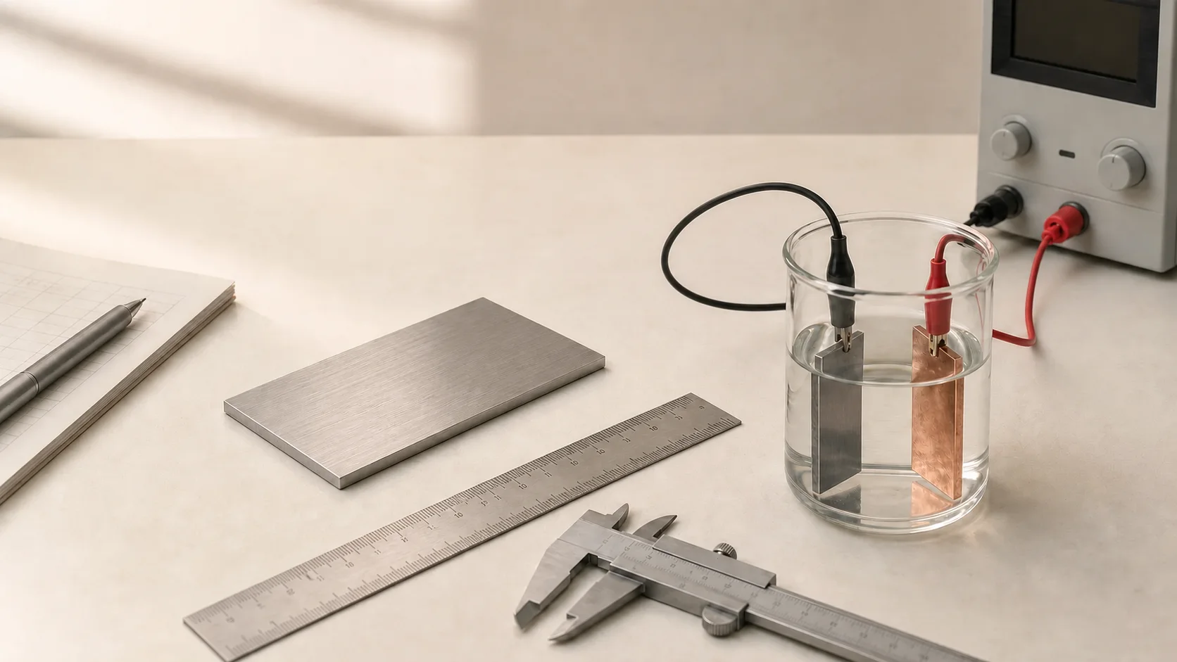 Measure every exposed surface before selecting a bath-specific current density and setting the power supply.
You can also calculate plating current with PlateLab through its Guided Plating workflow.
Electroplating current calculation at a glance
| Symbol | Meaning | Common unit |
|---|---|---|
| I | Required plating current | Amperes (A) |
| A | Total exposed cathode area | dm², cm², in² or ft² |
| J | Selected cathode current density | A/dm², A/cm² or A/ft² |
Formula: I = A × J
Required current = total plated area × selected current density
For example, a part with 1.5 dm² of exposed area at 3 A/dm² requires:
I = 1.5 dm² × 3 A/dm² = 4.5 A
The arithmetic is simple. The important work is measuring the complete area and obtaining a suitable current density for the exact bath. Bath chemistry, temperature, agitation, additives, anode arrangement and part geometry all affect its operating window. A supplier's technical data sheet takes precedence over a generic example.
Key facts
- Measure every exposed cathode surface that will receive metal.
- Exclude masked or electrically insulated areas.
- Convert area into the unit used by the bath specification.
- Obtain current density from the bath supplier or a validated process.
- Multiply area by current density.
- Treat the result as a controlled process setting, not the power supply's maximum output.
Why electroplating current is based on surface area
Current density is the electrical current applied per unit of plated surface area. It can also be written as J = I ÷ A.
The same amperage behaves differently on parts of different sizes. At 2 A, a 0.5 dm² part receives 4 A/dm², while a 2 dm² part receives only 1 A/dm². This is why amperage alone does not describe the intensity of an electroplating process.
Current density affects deposition rate, appearance, coverage and uniformity. Too much can produce dark, rough, powdery or burnt high-current areas. Too little can give slow deposition, dullness or poor coverage. Sharp edges and projections tend to attract more current, while recessed or shielded areas receive less. MISUMI's electroplating tutorial on Faraday's law likewise defines current density per unit area and describes total applied current as area multiplied by the applicable current density.
Step 1 — Calculate the total surface area
Include every surface that is submerged, electrically connected and exposed to the electrolyte: front and back faces, sides, ends, edges, accessible holes, bores and recesses. Add every part connected to the same rack. Exclude properly masked, plugged, lacquered or insulated areas that cannot receive metal.
Common surface-area formulas
| Shape and exposed surfaces | Formula |
|---|---|
| Rectangle, one face | A = L × W |
| Thin plate, both broad faces | A = 2LW |
| Rectangular component, all faces | A = 2(LW + LT + WT) |
| Cylinder, curved surface | A = πDL |
| Solid cylinder, curved surface and ends | A = πDL + 2πr² |
| Disc, one face | A = πr² |
| Disc, both faces and edge | A = 2πr² + 2πrt |
| Open tube, inner and outer walls | A = πDₒL + πDᵢL |
| Open tube, walls and both end rings | A = πDₒL + πDᵢL + 2π(rₒ² − rᵢ²) |
Use consistent dimensions. L is length, W width, T or t thickness, D diameter and r radius.
For a plate measuring 100 × 50 × 2 mm, one broad face is 5,000 mm² and both faces are 10,000 mm². If the edges are exposed, add their area too.
For an irregular part, divide the geometry into boxes, cylinders, discs and tubes, then add the sections. A checked CAD surface-area value is often the best option. Repeating features can be measured once and multiplied. Physical paper or film templates can help on suitable curved surfaces. Review CAD results for blind holes, threads, tiny fillets and fixture-covered regions that may not actually plate.
Step 2 — Convert the area into the required units
The area unit must match the denominator of the current-density unit.
| Conversion | Equivalent |
|---|---|
| 1 dm² | 100 cm² |
| 1 dm² | 10,000 mm² |
| 1 m² | 100 dm² |
| 1 in² | 6.4516 cm² |
| 1 in² | 645.16 mm² |
| 1 ft² | 9.2903 dm² |
| 1 A/dm² | 9.2903 A/ft² |
A component with 13,020 mm² of exposed area has:
13,020 ÷ 10,000 = 1.302 dm²
Do not multiply cm² by A/dm² or in² by A/ft². Always carry the units through the calculation so the area unit cancels:
1.302 dm² × 3 A/dm² = 3.906 A
Step 3 — Find the appropriate current density
Use the plating-bath supplier's technical data sheet whenever one is available. It may specify a current-density range together with required temperature, pH, agitation, metal concentration, anode type and rack or barrel operation.
Do not copy a value from an unrelated bath simply because it deposits the same metal. The Nickel Institute's Nickel Plating Handbook documents different operating conditions for Watts, sulphamate and semi-bright nickel formulations. Technic's Glance Cu 160 technical sheet, for example, specifies 1 A/dm² for that particular cyanide-free alkaline copper process. Neither value should be generalized to every nickel or copper bath.
When a data sheet gives a range, use its recommended starting point and remain inside the validated window. A conservative setting does not mean going below the supplier's minimum; insufficient current density can also produce a poor deposit.
Safety note: Electroplating solutions may contain acids, dissolved metals and additives that can harm skin, eyes or the respiratory system. Read the current Safety Data Sheet, use compatible eye and skin protection, provide suitable ventilation, label containers and follow local waste rules. The NIOSH guidance for nickel and nickel compounds identifies inhalation, ingestion and skin or eye contact as exposure routes and lists sensitization dermatitis and allergic asthma among possible effects.
Step 4 — Calculate the required current
Once area and current density use matching units, multiply them:
Surface area: 1.5 dm²
Selected current density: 3 A/dm²
I = A × J
I = 1.5 × 3
I = 4.5 A
Calculate first and round only at the end. A result of 3.906 A might become 3.90 A on a supply with 0.01 A resolution. Avoid aggressive rounding on small parts: raising 0.07 A to 0.10 A increases current density by about 43%.
Choose a regulated direct-current supply with constant-current control, fine enough adjustment and continuous capacity above the required value. A 10 A rating describes capacity; it does not mean the process should run at 10 A.
Worked electroplating current examples
The following current densities are illustrative assumptions, not universal nickel, copper or zinc bath settings.
Nickel-plated rectangular component
A 120 × 50 × 3 mm component has all six faces exposed:
A = 2[(120 × 50) + (120 × 3) + (50 × 3)] = 13,020 mm²
A = 1.302 dm²
At an assumed 3 A/dm²:
I = 1.302 × 3 = 3.906 A, or approximately 3.90 A.
Copper-plated cylindrical component
A solid cylinder is 40 mm in diameter and 80 mm long, with both ends exposed:
A = πDL + 2πr² = π(40)(80) + 2π(20²)
A ≈ 12,566 mm² = 1.2566 dm²
At an assumed 2 A/dm²:
I = 1.2566 × 2 = 2.5132 A, or approximately 2.50 A.
Zinc-plated batch of identical parts
Eight 60 × 25 × 2 mm tabs are plated together. One tab has:
A = 2[(60 × 25) + (60 × 2) + (25 × 2)] = 3,340 mm²
For eight tabs:
3,340 × 8 = 26,720 mm² = 2.672 dm²
At an assumed 1.5 A/dm²:
I = 2.672 × 1.5 = 4.008 A, or approximately 4.0 A.
Should voltage also be calculated?
In most bench setups, current is the controlled process target. Voltage is adjusted—or allowed to rise in constant-current mode—until the required current flows. The necessary voltage depends on electrolyte resistance, electrode spacing, anode and cathode area, contact and cable resistance, bath temperature, anode condition, part geometry and electrochemical polarization.
There is therefore no universal plating voltage that can be calculated from surface area alone. If the required current cannot be reached without exceeding the bath supplier's voltage guidance or the power supply's rating, stop and inspect the connections, contacts, spacing and electrolyte condition.
Common electroplating current calculation mistakes
- Counting only one face of a freely immersed part.
- Forgetting edges, holes, bores or accessible recesses.
- Including masked or insulated areas.
- Mixing cm², dm², in² or ft² with the wrong current-density unit.
- Confusing current in amperes with current density in amperes per unit area.
- Treating one chemistry's operating range as universal.
- Ignoring the combined area of multiple parts.
- Using the power supply's maximum output as the process setting.
Calculate electroplating current automatically with PlateLab
PlateLab Guided Plating asks for the plating metal, unit system, total cathode surface area, part geometry, bath type, bath volume, efficiency and target thickness. It returns Gentle, Balanced and Faster current-and-time recommendations, identifies practical limits and rounds suggested setup currents to usable increments.
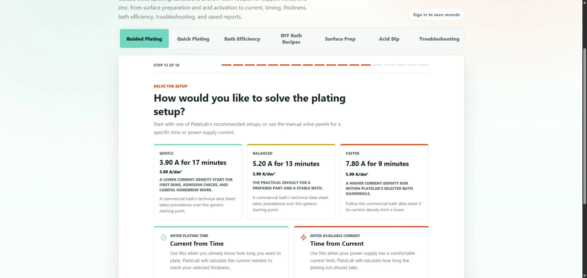 For 13,020 mm² of area, PlateLab's illustrative Gentle nickel setup shows 3.90 A at 3.00 A/dm². A commercial bath's technical data sheet still takes precedence.
Quick Plating provides a different workflow: it calculates current from area, thickness, efficiency and a desired time, or calculates time from an available current. It does not ask for current density as a direct input.
Calculate electroplating current from surface area with PlateLab.
For the complete process, read the PlateLab step-by-step electroplating guide. The PlateLab FAQ also explains bath efficiency, current rounding and geometry limits. You can learn more about the app on the Attalos PlateLab page.
Frequently asked questions
What is current density in electroplating?
Current density is electrical current divided by plated surface area. It is commonly expressed as A/dm² or A/ft².
Do I calculate both sides of the part?
Yes, if both sides are exposed and will receive metal. Include exposed edges, ends, holes and accessible internal surfaces too.
How do I estimate the area of an irregular part?
Divide it into simple shapes, use a checked CAD surface-area measurement, measure repeating features or use a physical template where appropriate. Document assumptions when precision is limited.
Should I calculate voltage or amperage?
Calculate amperage from surface area and current density. Voltage depends on the complete plating cell and is adjusted as needed to maintain that current.
What happens if the plating current is too high?
Excessive local current density can cause burnt edges, dark or powdery deposits, roughness, gas pitting and poor coverage in recesses.
Can I use the same current density for nickel, copper and zinc?
No. Current-density limits belong to the bath chemistry and operating conditions. Follow the technical data sheet for the exact product or validated formulation.
How do I calculate current for multiple parts?
Calculate one part's plated area, multiply by the number of identical parts, add any different components plated simultaneously and multiply the combined area by current density.
Final checklist
- Measure all exposed surfaces.
- Include both sides, edges, holes and accessible recesses.
- Exclude masked or insulated areas.
- Convert area into the bath specification's unit.
- Obtain a bath-specific current density.
- Multiply area by current density.
- Verify that the power supply can maintain the result.
- Confirm polarity: anode positive and workpiece negative.
- Prepare PPE, ventilation, rinsing and spill controls.
- Start within the validated operating range and monitor the deposit.
The calculation is I = A × J. A reliable result depends on complete surface-area measurement, matching units and a current-density value that belongs to the actual plating bath.
Written and technically reviewed by Ersin Aytaç, creator of PlateLab. Publication and updated dates are displayed by Attalos Life when the article is published.